
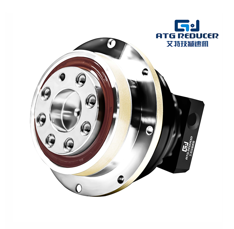
An ATG gear reducer is a mechanical power transmission device designed to reduce rotational speed while increasing output torque.
In many industrial and automation applications, gear reducers are essential for matching motor speed to the working speed required by machines,
improving load control, efficiency, and system stability. Understanding the ATG gear reducer working principle helps engineers,
buyers, and maintenance teams select the right gearbox for conveyors, mixers, packaging systems, hoists, robotics, and general machinery.
This guide explains the ATG gear reducer working principle, main components, gearbox ratios, performance factors, advantages, types,
specifications, and common application scenarios. The content is written in a search-friendly structure and is suitable for blog pages,
category pages, industry landing pages, and technical resource sections.
An ATG gear reducer is a speed-reduction transmission unit that uses gear meshing to convert high-speed, low-torque input into lower-speed,
higher-torque output. In practical terms, a motor may rotate too fast for direct machine use. The gear reducer lowers the speed to a usable level
while multiplying torque, making the machine easier to control and more efficient under load.
The term ATG gear reducer is commonly used in industrial search queries to describe a gear reduction system built for durable
mechanical power transmission. While different product structures exist, the working principle remains the same: input rotation passes through
one or more gear stages, and the output shaft rotates more slowly with higher force.
The ATG gear reducer working principle is based on gear ratio. When a small driving gear turns a larger driven gear,
the speed decreases and torque increases. This mechanical advantage is the core function of every gear reducer.
In a typical gearbox, the motor supplies rotational energy to the input shaft. The input shaft drives gears inside the housing.
Depending on the design, the gearbox may use spur gears, helical gears, bevel gears, worm gears, planetary gears, or a combination of stages.
Each stage changes speed and torque according to the tooth count ratio.
If the input gear has fewer teeth than the output gear, the output shaft rotates more slowly. Because power is transferred through a mechanical
system, the output torque rises proportionally, minus a small loss due to friction and heat. This is why gear reducers are widely used in
industrial systems that require strong force and stable motion.
Gear ratio is one of the most important terms in the ATG gear reducer working principle. It describes the relationship between
input and output speed. A 5:1 ratio means the input shaft must rotate five times for the output shaft to rotate once.
The higher the reduction ratio, the lower the output speed and the higher the torque multiplication. However, larger ratios may also introduce
more internal friction and sometimes lower mechanical efficiency, depending on the gear type.
| Gear Ratio | Input Speed | Output Speed | Torque Effect | Typical Use |
|---|---|---|---|---|
| 3:1 | High | Moderately reduced | Moderate torque increase | Light conveyor systems |
| 5:1 | High | Noticeably reduced | Strong torque gain | Packaging and automation |
| 10:1 | High | Significantly reduced | High torque increase | Material handling |
| 20:1 | Very high | Low | Very high torque output | Mixers and heavy-duty loads |
| 50:1 and above | Very high | Very low | Maximum torque multiplication | Precision or high-load applications |
To understand the ATG gear reducer working principle, it is useful to know the key components inside the unit. Each part has a
direct role in speed reduction, torque transmission, and long-term reliability.
| Component | Function |
|---|---|
| Input shaft | Receives rotation from the motor or drive source |
| Gears | Transmit motion and create the speed reduction effect |
| Output shaft | Delivers reduced-speed, high-torque rotation to the load |
| Bearing system | Supports shafts and reduces friction during operation |
| Housing | Protects internal parts and maintains structural alignment |
| Lubrication system | Reduces wear, heat, and mechanical losses |
| Seals | Prevent oil leakage and keep contaminants out |
The phrase ATG gear reducer can apply to several gearbox structures. Each structure has a different working style, efficiency level,
and torque capacity. Choosing the right type depends on the required speed reduction, mounting style, load demand, and installation space.
| Reducer Type | Working Principle | Key Advantage | Common Application |
|---|---|---|---|
| Helical gear reducer | Uses angled teeth for smoother engagement | Low noise and high efficiency | Conveyors, fans, mixers |
| Spur gear reducer | Uses straight teeth for direct transmission | Simple design and easy maintenance | General machinery |
| Worm gear reducer | Uses worm and wheel to create a large ratio | Compact and high reduction ratio | Hoists, lifts, indexing systems |
| Planetary gear reducer | Uses central sun gear and planet gears for load sharing | High torque density and precision | Automation, robotics, servo systems |
| Bevel gear reducer | Transfers motion between intersecting shafts | Changes rotation direction efficiently | Right-angle drive systems |
A common question in gear reducer searches is why torque increases when speed decreases. The answer lies in conservation of power.
Power is the product of torque and speed. When a reducer lowers speed, it increases torque in proportion, minus losses from friction.
This mechanical trade-off is highly valuable. Motors are often optimized for fast rotation, but machines may require slow, forceful motion.
The ATG gear reducer working principle solves this mismatch by converting motor speed into practical working torque.
Gear reducers are widely used because they offer several practical advantages in mechanical systems. For SEO and industry content, these benefits
are important because they explain why searchers look for the ATG gear reducer working principle in the first place.
| Benefit | Description |
|---|---|
| Speed reduction | Adjusts motor output to a usable machine speed |
| Torque multiplication | Increases force for heavy-duty operation |
| Stable motion | Helps maintain smooth and controlled movement |
| Improved load handling | Supports higher working loads without overloading the motor |
| Energy efficiency | Helps motors operate within a practical speed range |
| Long service life | Durable construction supports continuous industrial use |
| Compact system design | Allows strong output in a relatively small space |
When evaluating an ATG gear reducer or similar industrial gearbox, buyers often compare technical specifications. These specs help determine whether
the reducer is suitable for the application, environment, and duty cycle.
| Specification | Typical Range or Meaning |
|---|---|
| Input speed | Depends on motor speed, often 1000 to 3600 rpm |
| Output speed | Reduced speed based on gear ratio, often below 300 rpm in many systems |
| Gear ratio | Common ranges from 3:1 to 100:1 or more |
| Rated torque | The maximum continuous torque the reducer can handle |
| Efficiency | Varies by gear type, often from moderate to high |
| Mounting type | Foot-mounted, flange-mounted, shaft-mounted, or inline |
| Lubrication | Oil bath, grease, or forced lubrication depending on design |
| Protection level | May include dust and moisture resistance for industrial environments |
Ratio selection is one of the most important steps in gearbox application. The right ratio depends on the target output speed, required torque,
motor speed, and machine load. A correct ratio ensures efficient operation and avoids underperformance or overload.
In many industrial systems, a lower ratio may be enough for light loads, while a higher ratio is needed for heavy resistance or precision control.
The ATG gear reducer working principle remains the same, but the performance result changes significantly with ratio selection.
Gear reducers are used across many industries because they solve a universal problem: converting fast motor speed into usable machine force.
The following applications are among the most common search topics related to the ATG gear reducer working principle.
| Industry | Typical Use Case | Why a Gear Reducer Is Needed |
|---|---|---|
| Material handling | Conveyors, rollers, sorting lines | Stable speed and controlled torque |
| Food processing | Mixers, packaging, filling systems | Smooth operation and repeatable motion |
| Manufacturing | Assembly equipment, machine tools | Load support and speed matching |
| Mining and construction | Heavy-duty drives, crushers, feeders | High torque under demanding conditions |
| Automation | Servo drives, indexing tables, robotics | Precision control and compact transmission |
| Water treatment | Agitators, clarifiers, dosing systems | Reliable continuous-duty performance |
The efficiency of an ATG gear reducer depends on how well the internal parts work together. Even though the gear reducer principle is simple,
real-world performance is affected by mechanical and operating conditions.
Proper maintenance is essential for preserving the performance of any gear reducer. If a gearbox is used in continuous industrial service,
preventive maintenance can reduce downtime and improve reliability.
| Maintenance Task | Recommended Purpose |
|---|---|
| Check oil level | Ensures sufficient lubrication |
| Inspect oil condition | Detects contamination, wear, or overheating |
| Examine seals | Prevents leakage and contamination |
| Monitor vibration | Identifies imbalance or misalignment |
| Check temperature | Helps detect overload or friction issues |
| Tighten mounting bolts | Maintains mechanical stability |
| Replace worn lubricant | Supports long-term gear protection |
Knowing the warning signs of gearbox issues can help prevent costly failures. Since the ATG gear reducer working principle depends on
smooth gear meshing and proper lubrication, any deviation can affect speed, torque, noise, and reliability.
For content creators building a blog, category page, or industry landing page, the keyword ATG gear reducer working principle explained
can be supported by clear definitions, structured headings, comparison tables, and application-focused sections. Search engines typically reward
content that answers user intent thoroughly and clearly.
A strong gear reducer page should include the meaning of the product, how it works, technical specifications, benefits, use cases, and selection tips.
This allows the page to rank for related queries such as gear reducer working principle, industrial gearbox ratio,
torque increase by gearbox, and gear reducer applications.
The following keyword phrases are commonly associated with the topic and can support semantic SEO when used naturally in surrounding content:
The ATG gear reducer working principle is based on a simple but powerful idea: use gear meshing to reduce speed and increase torque.
This makes industrial machines more practical, efficient, and stable. By understanding gear ratio, gearbox types, major components, performance
factors, and maintenance needs, users can better evaluate the right reducer for their application.
Whether the application is conveyor movement, mixer operation, automation control, or heavy-duty mechanical transmission, a gear reducer remains
one of the most important components in industrial drive systems. With the right specification and proper maintenance, an ATG gear reducer can
provide reliable performance, smooth operation, and long service life.
Trang web này sử dụng cookie để đảm bảo bạn có được trải nghiệm tốt nhất trên trang web của chúng tôi.

 Chinese
 EN
EN Español
 Pусский
 Deutsch


 Điện thoại
Bình luận
(0)